The details below provide examples of installation illustrations and the steps required to install and configure a Repeater Transmitter and its components.
Location is extremely important to ensure the best operation of the system. The Repeater Transmitter must be in a location where it can receive a signal from the main Transmitter.
Note
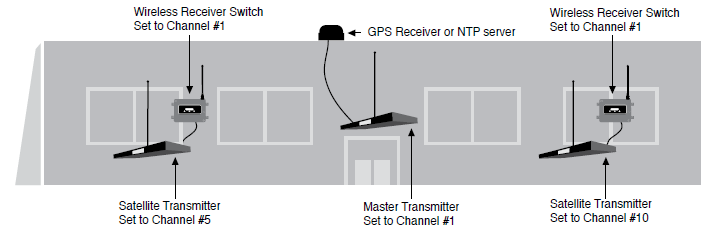
Do not adjust the channel numbers on the Transmitter as illustrated below. The examples only demonstrate how a repeater switch chain works
Example of system with horizontal installation
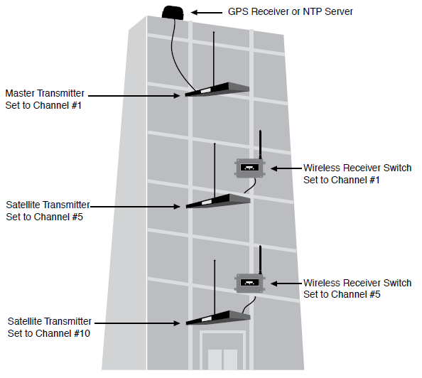
Example of a system with vertical installation
The following tools and equipment are recommended and can be purchased from Primex.
1 Watt Transmitter Shelf. 18 GA metal, epoxy coated, 18 in. L x 3 in. H x 16.5 in. D
Uninterrupted Power Supply (UPS)
Location and mounting must meet all of the following requirements.
Multi-story building: locate main Transmitter on the top floor; significantly improves coverage to the lower floors due to the “umbrella” pattern of transmission
Transmitter mounting location: a minimum of 4 ft. (1.2 m) above the floor.
Transmitter shelf mounting: 18 in.L x 3 in. W x 16.5 in. mounting shelf available from Primex.
-
Transmitter enclosure clearance: located in an area that allows for required clearance.
Enclosure dimension: 2 in. H x 17 in. W x 12 in. D (5.08 cm x 43.18 cm x 30.48 cm). Required wall area is 24 in. W x 18 in D.
Allow a minimum of 43 in. (1.09 m) vertical clearance; includes internal antenna 40.8 in. H (1.03 m) and Transmitter enclosure height of 2 in. (5.08 cm)
Internal antenna clearance: requires vertical clearance and distance of a minimum 5 ft. (1.5 m) from large, solid objects, such as lockers or filing cabinets. Antenna should never make contact with metal objects, especially electrical conduit or wiring of any kind, and proximity to these should be avoided. Internal Antenna height: 40.8 in. (1.03 m).
-
AC power: located within 5 ft. (1.5 m) from a 120 VAC electrical outlet. 10 AMP dedicated service recommended.
AC power supply (supplied): Input: 120 VAC, 50/60 Hz, 0.6 Amp. Output: 9 VDC, 1.78 Amp. 6 ft. (1.83 m) cord
Environment: located in an indoor controlled environment that is 32° to 122° F (0° to 50° C) and a non-condensing humidity environment.
The main Transmitter must be set up and working prior to installation of the Repeater Transmitter.
Complete the steps below to set the preferences of a XR Repeater (Satellite) Transmitter. The setting panel is located on the back of the unit.

Set Channel Number. It's recommended to have a four channel separation between adjacent Transmitters.
-
Set the Time Zone rotary switch for the correct Time Zone:
Turn to 4 for Atlantic Time Zone
Turn to 5 for Eastern Time Zone
Turn to 6 for Central Time Zone
Turn to 7 for Mountain Time Zone
Turn to 8 for Pacific Time Zone
Turn to 9 for Alaska Time Zone
Turn to A for Hawaii Time zone
Turn to 0 for Greenwich Mean Time (GMT)
-
Set LCD display time mode: set dip switch #8 to 12H or 24H
Flip switch to the UP position to select 24 hour time
Flip switch to the DOWN position to select 12 hour time
-
Set the LCD display to either Standard Time (ST) or Daylight Saving Time (DST)
Dip switch #7 (ST/DST): set to the UP position to disable Daylight Saving Time (DST) on the Repeater (Satellite) Transmitter.
Where applicable, DST changes are configured from the Receiver Switch.
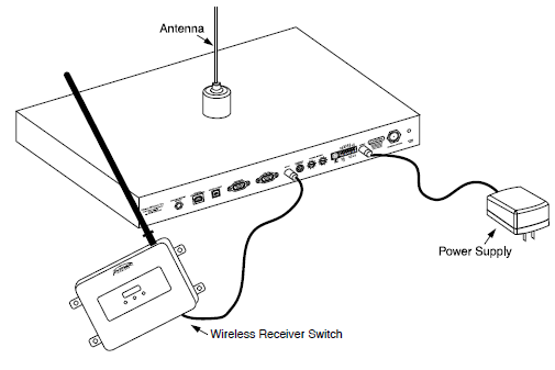
Carefully screw the antenna onto the unit. Turn the antenna clockwise being careful to avoid cross-threading the antenna. The base of the antenna must be snug against the case.
Plug the supplied 9 Volt/2.78A Amp power supply into the Transmitter.
Plug the power supply into a 120 VAC outlet.
Step 3: Set up Receiver Switch
To access the Receiver Switch menu preferences, press the Menu button located on the front of the unit. By pressing and holding the Menu button, the Receiver Switch cycles through the menu options.
While in the Channel menu option, if there are no changes made in a minute of entering a menu section, it will time out and save the displayed value and exit the menu mode.
If a value is changed while cycling through the menu, it will be saved and continue to cycle.
While in test mode, it will remain in the selected mode until the menu button is pressed again to exit.
After entering changes, it's recommended to step through the menu options until the option donE is displayed to exit the menu mode; the menu will display donE. Changes made in the Menu are saved when the menu is exited.
Receiver Switch menu mode option specifications
Display |
Menu |
Description |
|---|---|---|
Ch |
Channel |
The Channel Number menu allows the user to change the channel by using the UP or DOWN button. The channel number must be set to the same channel number as the Main Transmitter or other Repeater (Satellite) Transmitter broadcast channel. |
tESt |
Test |
The Test menu allows the user to hear audible beeps with a valid time/date reception. This occurs 5 seconds after the test menu is selected. It continued to be in this mode until the menu button is pressed again, leaving the menu mode and returning to normal mode. |
LtU |
Last Time Update |
The Last Time Update menu allows the user to see the last time update, time and date (cycles every second). This occurs 5 seconds after last time update menu is selected. The unit remains in this mode for a minute, it will then time out and return to the menu mode. |
Soft |
Software Revision |
The Software Revision menu allows the user to see the software revision on the unit. his occurs 5 seconds after last time update menu is selected. The unit remains in this mode for a minute, it will time out and return to the menu mode. |
dst |
Daylight Saving Time Calendar |
The Daylight Saving Time Calendar menu allows the user to see the current Daylight Saving Time calender in use. This occurs 5 seconds after last time update menu is selected. The unit remains in this mode for a minute, it will time out and return to the menu mode. |
donE |
Done |
The Done menu allows the user to exit the menu mode. This occurs 5 seconds after the done menu is selected returning to the normal mode and save all settings. |
The Receiver Switch has an internal dip switch panel that sets the configuration for the time/date display, automatic Daylight Saving Time, and automatic channel scanning.
-
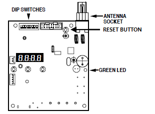
To access the dip switch panel, remove the unit's large cover. Remove the two Phillip head screws, located in the upper left and lower right of the unit. The dip switch panel is located on the top of the unit; identified by the blue switch panel.
Note
Except when setting the dip switch options, the unit cover should remain closed and secure at all times.
Switch |
Sets the... |
ON Position |
OFF Position |
|---|---|---|---|
2 |
Time/Date |
Displays only the time. |
Displays current time for 8 seconds and the date for 2 seconds. |
3 |
12/24 Hour |
Displays the time in 24 hour format. |
Displays the time in 12 hour format. |
4 |
RF Channel Scan |
Enable the scan and look for a suitable channel. |
Disable the scan and only look on the selected channel for time/date/event info. |
5 |
Daylight Saving Time - DST |
DST is disabled Only for geographic areas that do not observe Daylight Saving Time (DST), the Receiver Switch must be configured to bypass DST. In the event the Receiver Switch does not receive a Transmitter signal when the DST change is scheduled to occur, the switch automatically adjusts its time received from a Transmitter. In areas that do not observe DST, this feature must be disabled on the circuit board of the Receiver Switch |
DST is enabled |
6, 7, 8 |
Does not apply to the use of this unit. |
||
Attach the rubber antenna to the Receiver Switch.

Power down the Repeater (Satellite) Transmitter.
-
Connect the serial cable of the Receiver Switch into the GPS IN Socket on the back of the Repeater (Satellite) Transmitter.
Power on the Repeater (Satellite) Transmitter.
Press the Menu (middle button) on the front of the unit to scroll through the Menu options to the Channel Mode (Ch displayed).
Press the UP or DOWN button to set the channel number to match the Main Transmitter's transmit channel.
Scroll through the menu to the donE mode. After 5 seconds the Receiver Switch will time-out and return to the Time/Date mode saving the channel selection.
-
Determine the best mounting location for the Receiver Switch.
Locate the room/area the Transmitter is to be installed in. Close all doors and windows before testing.
DO NOT hold the rubber antenna during testing, as this can affect the sensitivity of the receiver. Instead, hold the switch by the sides of the housing while locating the best mounting position.
Place the Receiver Switch in the EXACT location where it will be mounted. This is crucial as closeness to walls can degrade receiver sensitivity. If the exact location is not known, be sure to test the Receiver Switch in several locations. If any locations tested are unsuccessful, note this for future reference.
-
Power Cycle the Receiver Switch power at least 1-2 times after installation is complete and verify the green LED begins to flash. Doing this will ensure a solid signal is being received.
To power cycle the Receiver Switch, remove the switch cover by removing the two Phillip head screws located in the upper left and lower right of the unit. Use caution when removing the cover to avoid causing the up or down menu buttons to fall off the circuit board.
Press and release the Reset button, located in the upper right corner to the left of the antenna mounting, 1 to 2 times and verify the green LED begins to flash. The flashing of the green LED indicates a solid signal is being received.
Mount the Receiver Switch in its final location and verify the switch settings.
Note
When the Receiver Switch is mounted, its antenna must be vertical. Do not use an analog clock to determine if a mounting location will be adequate for signal reception. The receiver in a clock is more sensitive than the Receiver Switch and therefore the switch may not work in areas where a clock works.
When the Receiver Switch is connected to the powered Repeater (Satellite) Transmitter, an R is displayed in the upper right corner of the Transmitter's front panel display. This may take up to a minute.
The green RX LED on the Wireless Receiver Switch will flash when a valid signal is initially received. This LED will then flash once per second, signifying a successful time update. If the green LED is solid, the Receiver Switch missed the last update. Time updates occur once per hour.
Note
If the Repeater (Satellite) Transmitter does not receive a time update from the Receiver Switch after 48 hours, its yellow “Caution” LED begins flashing and an error is logged.
To verify the last time the Receiver Switch received and applied a valid time/date update, toggle through its menu to the Last Time Update (LTU) section.
When there are multiple Repeater Transmitters, you will need to set the channel number for each Repeater Transmitter. Prior to shipment, Primex does set the channel number to the number printed on the red label on the top its packaging box.
From the Receiver Switch LED menu, use the buttons to toggle to the channel number menu, and set the channel number to the strongest available signal. This signal may be from either the main Transmitter or the nearest Repeater Transmitter.
After changing the channel, power cycle the Receiver Switch. Remove its cover by removing the two Phillip head screws, located in the upper right and lower right of the unit. Use caution when removing the cover to avoid causing the up or down menu buttons to fall off the circuit board.
Press and release the Reset button, located in the upper right corner to the left of the antenna mounting, one to two times and verify the green LED begins to flash. The flashing of the green LED indicates a solid signal is being received.