Parameter |
Specification |
|---|---|
Operating Frequency Range |
72MHz |
Channels |
49 channels available (pre-programmed prior to shipping) |
Channel Bandwidth |
20KHz |
Maximum Transmission |
1 Watt (at Transmitter) |
Radio Technology |
Narrowband FM |
Bluetooth Technology |
Bluetooth® low energy (v5) wireless technology. To allow pairing with OneVue Device Configurator (ODC) app for configuration and setting management. |
User-defined Settings |
Locally at device with OneVue Device Configurator (ODC) app
OneVue software
|
Dimensions |
17 in. L x 12 in. W x 1.7 in. D (43.2 cm x 30.5 cm 4.32 cm) |
Weight |
9 lb. (4.08 kg) |
Power Supply |
Input: 120 VAC, 50/60 Hz, 0.6 Amp. Output: 9 VDC, 1.78 Amp. 6 ft. (1.83 m) cord |
Antenna |
Type: Whip Antenna Height: 3.4 ft. (1.03 m) Mounting: thread |
Front Panel |
Four LED status indicators (Power, Transmit, Caution, Error) and Bluetooth labeled push-button to pair with the Primex OneVue Device Configurator (ODC) app. |
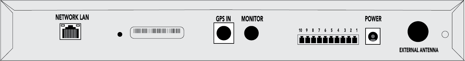
Rear Panel |
DC Input: connection to supplied AC power supply Network LAN port: RJ-45 Ethernet, 10/100 Mbps, 802.3 Ethernet GPS IN port: MiniDIN 7-Pin Dry Contact Closure Terminal Block with removable connector: for use with OneVue Notify with Critical Notifications Pinhole button: initiate manual check-in to OneVue (press and release with jewelers screwdriver or other small object) |
Top Panel |
Internal Antenna connection. |
Operating Range |
32° to 122° F (0° to 50° C), non-condensing environment |
Warranty |
5 Year |
Canadian Notice: The manufacturer rated output power of this equipment is for single carrier operation. For situations when multiple carrier signals are present, the rating would have to be reduced by 3.5 dB, especially where the output signal is re-radiated and can cause interference to adjacent band users. This power reduction is to be by means of input power or gain reduction and not by an attenuator at the output of the device.
All specifications are subject to change without notice.
Parameter |
Specification |
|---|---|
Operating Frequency Range |
72MHz |
Channels |
49 channels available (pre-programmed prior to shipping) |
Channel Bandwidth |
20KHz |
Maximum Transmission |
1 Watt (at Transmitter) |
Radio Technology |
Narrowband FM |
Bluetooth Technology |
Bluetooth® low energy (v5) wireless technology. To allow pairing with OneVue Device Configurator (ODC) app for configuration and setting management. |
User-defined Settings |
Locally at device with OneVue Device Configurator (ODC) app
OneVue software
|
Dimensions |
17 in. L x 12 in. W x 1.7 in. D (43.2 cm x 30.5 cm 4.32 cm) |
Weight |
9 lb. (4.08 kg) |
Power Supply |
Input: 120 VAC, 50/60 Hz, 0.6 Amp. Output: 9 VDC, 1.78 Amp. 6 ft. (1.83 m) cord |
Front Panel |
Four LED status indicators (Power, Transmit, Caution, Error) and Bluetooth labeled push-button to pair with the Primex OneVue Device Configurator (ODC) app. |
Rear Panel |
DC Input: connection to supplied AC power supply Network LAN port: RJ-45 Ethernet, 10/100 Mbps, 802.3 Ethernet GPS IN port: MiniDIN 7-Pin External Antenna connector (coaxial, n-male) Dry Contact Closure Terminal Block with removable connector: for use with OneVue Notify with Critical Notifications Pinhole button: initiate manual check-in to OneVue (press and release with jewelers screwdriver or other small object) Not applicable to model: Baseboard Monitor port (MiniDIN 9-Pin) |
Operating Range |
32° to 122° F (0° to 50° C), non-condensing environment |
Warranty |
5 Year |
Canadian Notice: The manufacturer rated output power of this equipment is for single carrier operation. For situations when multiple carrier signals are present, the rating would have to be reduced by 3.5 dB, especially where the output signal is re-radiated and can cause interference to adjacent band users. This power reduction is to be by means of input power or gain reduction and not by an attenuator at the output of the device.
All specifications are subject to change without notice.
This topic provides the requirements and procedures to install a 1 Watt Transmitter with an internal antenna.
Install GPS Receiver (if applicable to system)
Mount Transmitter
Establish Transmitter connection and power on
Configure Transmitter with OneVue Device Configurator (ODC) app
Verify Transmitter operation
Install additional system devices
For a system with more than one Transmitter, first configure and install the main Transmitter and verify it received a valid time signal and then configure Repeater Transmitters. When all Transmitters are configured and installed, you can then configure and install the system clocks or InfoBoards.
Do not install system clocks and other devices until Transmitter and its components are installed and configured; powered on, time source configured and valid time signal received, and fully operational.
Review all installation requirements and identify the installation location of the Transmitter and system components.
Review all Safety Instructions and Warnings.
Inspect system components to verify packaging includes all supplied parts for each system component and verify no damage has occurred during shipping.
When planning the system installation of a Transmitter with an internal antenna, Primex recommends taking into consideration the below requirements. Location is extremely important to ensure the best operation of your system.
Location and mounting must meet all of the following requirements.
Multi-story building: locate the main Transmitter on the top floor; significantly improves coverage to the lower floors due to the “umbrella” pattern of transmission.
Transmitter mounting location: a minimum of 4 ft. (1.2 m) above the floor.
Transmitter shelf mounting: 18 in. L x 3 in. W x 16.5 in. (45.72 cm x 7.63 cm x 41.91 cm) mounting shelf available from Primex.
-
Transmitter enclosure clearance: located in an area that allows for required clearance.
Enclosure dimension: 2 in. H x 17 in. W x 12 in. D (5.08 cm x 43.18 cm x 30.48 cm). Required wall area is 24 in. W x 18 in D (60.96 cm x 45.72 cm).
Allow a minimum of 43 in. (1.09 m) vertical clearance; includes internal antenna 40.8 in. H (1.03 m) and Transmitter enclosure height of 2 in. (5.08 cm).
Internal antenna clearance: requires vertical clearance and distance of a minimum 5 ft. (1.5 m) from large, solid objects, such as lockers or filing cabinets. Antenna should never make contact with metal objects, especially electrical conduit or wiring of any kind, and proximity to these should be avoided. Internal Antenna height: 40.8 in. (1.03 m).
-
AC power: located within 5 ft. (1.5 m) from a 120 VAC electrical outlet. 10 AMP dedicated service recommended.
AC power supply (supplied): Input 120 VAC, 50/60 Hz, 0.6 Amp. Output 9 VDC, 1.78 Amp. 6 ft. (1.83 m) cord.
Ethernet connection (OneVue Monitor and NTP time source): located in close proximity to an Ethernet port.
Environment: located in an indoor controlled environment that is 32° to 122° F (0° to 50° C) and a non-condensing humidity environment.
The following tools and equipment are recommended and can be purchased from Primex.
1 Watt Transmitter Shelf. 18 GA metal, epoxy coated, 18 in. L x 3 in. H x 16.5 in. D
Uninterrupted Power Supply (UPS)
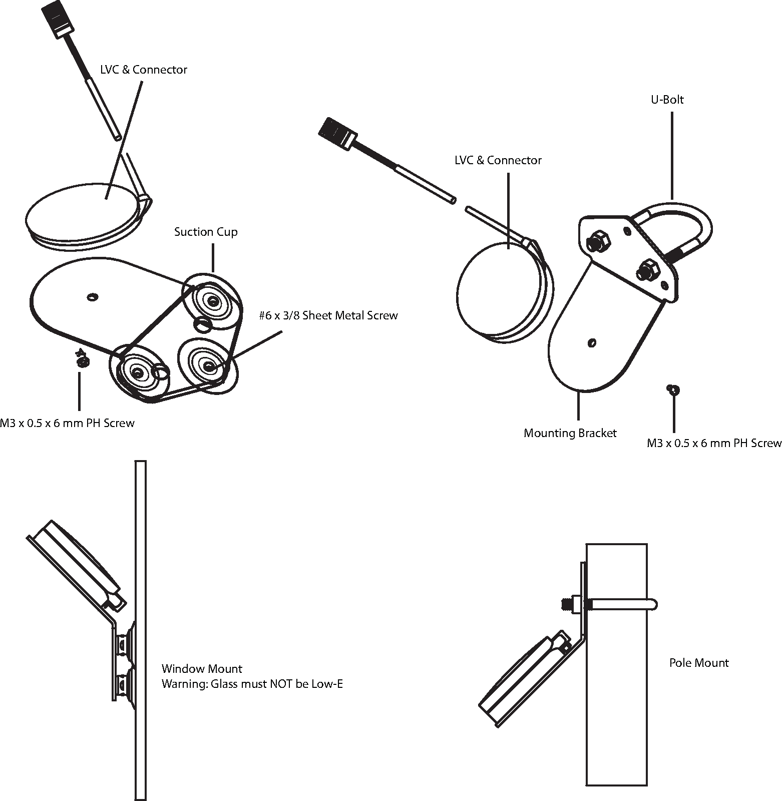
GPS Receiver location
Must be mounted where it has a "clear view of the sky" to receive a GPS signal 24 hours a day.
Typical mounting locations include the inside of a window (not a Low-E glass window), to an exterior pole, or on a rooftop.
Must be kept away from large metal objects.
GPS Receiver and cable must be mounted above any potential standing water, snow depth, leaves or other obstructions and is protected from the weather.
GPS cable
10 ft. (3 m) GPS cable supplied. Extension cables available from Primex.
Maximum total distance of the GPS cable to the Transmitter cannot exceed 200 ft. (60.96 m).
GPS cable located outdoors: cable routing to the inside of the building requires 2 in. (5 cm) minimum conduit and weatherhead. The use of a GelWrap splice enclosure is strongly recommended.
GPS and extension cables connections must be weatherproofed.
Supplied Ferrite Bead is required to be attached to the GPS cable to prevent electromagnetic interference (EMI) between the Transmitter and GPS Receiver. Ferrite Bead should be located no greater than an inch from the end of the GPS cable – as near as possible to the Transmitter GPS IN input connection.
A GPS Receiver is required when a Transmitter is set to use GPS as its time source. If GPS is not the time source, proceed to Step 2.
Mount GPS Receiver
Verify the kit contents and the installation location meets the installation guidelines.
From the outside of the building, route the GPS cable.
-
Assemble and mount the GPS Receiver unit to either the inside of a window (not Low-E glass) or to an outside pole or rooftop. The mounting location is required to have a clear view of the sky.
Note
Be sure to follow local building code requirements when attaching the GPS unit to the inside of a window. Clean the windowpane before using the suction cups for attachment.
Route GPS cable and connect to Transmitter GPS connection.
During this step, wire the critical notification input source to the Transmitter contact closure terminal block. Additional details provided below.
Critical Notifications are triggered by an end user from the five-button Critical Notification Panel or by a third-party system hardwired to the main Transmitter's industry standard contact closure panel.
The critical notification events displayed on InfoBoards are commonly be defined by your facility's emergency response plan. By default these events are preset by Primex and can be customized with a OneVue Notify Monitor subscription. A customization is defined as a change made to the Primex preset characters displayed by InfoBoards during a critical notification event.
To customize the preset events displayed on InfoBoards, see topic Customize preset critical notification events. A customization requires validation of the hardwired interface and thorough testing must be performed.
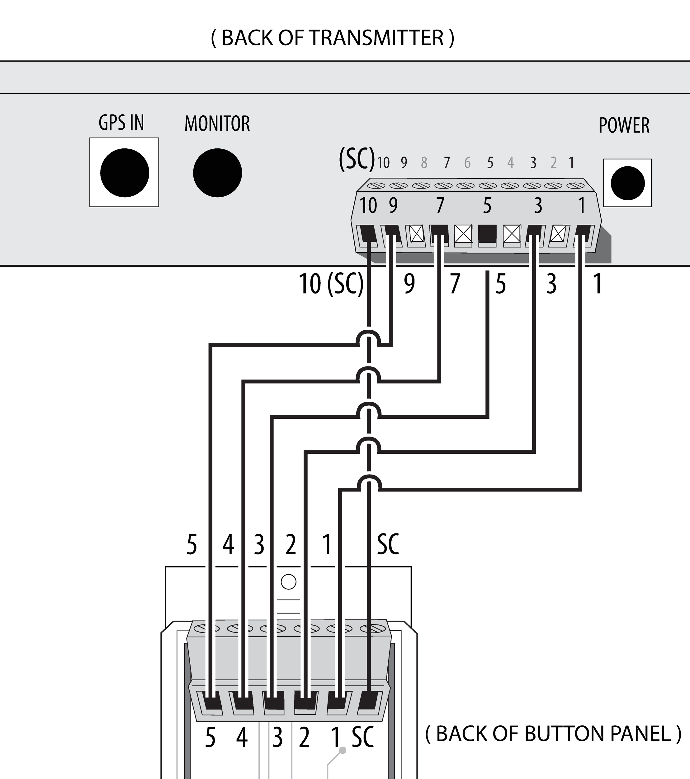
The Critical Notification Panel requires a hardwired interface between its dry contact terminal block and the main Transmitter's dry contact closure terminal block. This interface provides the activation of critical notification events displayed on Notify InfoBoards.
A Critical Notification Panel has five individually controlled contact closure switches and one common ground. Each switch corresponds to the panel's five buttons that change the state of each switch. A switch state change is activated from a momentary button push, which triggers an input state change to the Transmitter dry contact closure terminal block over the hardwired interface. An input state change activates the corresponding event number that is immediately transmitted over the 72MHz wireless radio frequency. When an InfoBoard receives an event number, it displays the corresponding event number description stored locally on the InfoBoard.
The main Transmitter supports up to two parallel Critical Notification Panel interfaces. Each interface requires a single cable run between the Critical Notification Panel and the main Transmitter contact closure terminal block.
Wire Color* |
Panel Position (L to R) |
Transmitter Position (L to R) |
Activates Preset Event |
|---|---|---|---|
Green |
5 |
9 |
All Clear |
Gray |
4 |
7 |
Lockout |
Yellow |
3 |
5 |
Weather |
Blue |
2 |
3 |
Evacuate |
Red |
1 |
1 |
Lockdown |
Black |
SC |
10 |
n/a (common ground) |
* Per Primex supplied interface cable wiring color specifications. Isolate any non-used wires.
The last step is to configure the Transmitter with the OneVue Device Configurator (ODC) app. A Transmitter will not operate until it's configured.
OneVue Sync Transmitters can be configured for OneVue Monitor or for Standalone use. To receive remote support services from Primex, OneVue Monitor configuration is required. For Transmitters that are part of a OneVue Monitor subscription, they must be configured for OneVue Monitor use.
Install external components, including external antenna and GPS Receiver.
Mount Transmitter.
Establish Transmitter connections and power on.
Configure Transmitter with OneVue Device Configurator (ODC) app.
Install additional system devices.
For a system with more than one Transmitter, first configure and install the main Transmitter and verify it received a valid time signal and then configure Repeater Transmitters. When all Transmitters are configured and installed, you can then configure and install the system clocks or InfoBoards.
Do not install system clocks and other devices until Transmitter and its components are installed and configured; powered on, time source configured and valid time signal received, and fully operational.
Review all installation requirements and identify the installation location of the Transmitter and system components.
Review all Safety Instructions and Warnings.
Inspect system components to verify packaging includes all supplied parts for each system component and verify no damage has occurred during shipping.
When planning the system installation of a Transmitter with an external antenna, Primex recommends taking into consideration the below guidelines. Location is extremely important to ensure the best operation of your system.
Location and mounting of a Transmitter with an external antenna must meet all of the following requirements.
Multi-story building: locate the main Transmitter on the top floor; significantly improves coverage to the lower floors due to the “umbrella” pattern of transmission.
Transmitter mounting location: a minimum of 4 ft. (1.2 m) above the floor.
Transmitter shelf mounting: 18 in. L x 3 in. W x 16.5 in. (45.72 cm x 7.63 cm x 41.91 cm) mounting shelf available from Primex.
-
Transmitter enclosure clearance: located in an area that allows for required clearance.
Enclosure dimension: 2 in. H x 17 in. W x 12 in. D (5.08 cm x 43.18 cm x 30.48 cm). Required wall area is 24 in. W x 18 in D (60.96 cm x 45.72 cm).
-
AC power: located within 5 ft. (1.5 m) from a 120 VAC electrical outlet. 10 AMP dedicated service recommended.
AC power supply (supplied): Input 120 VAC, 50/60 Hz, 0.6 Amp. Output 9 VDC, 1.78 Amp. 6 ft. (1.83 m) cord.
Ethernet connection (OneVue Monitor and NTP time source): located in close proximity to an Ethernet port.
Environment: located in an indoor controlled environment that is 32° to 122° F (0° to 50° C) and a non-condensing humidity environment.
Location and mounting of an external antenna must meet all of the following requirements.
Located within 100 ft. (30.48 m) from Transmitter. LMR 400 cable cannot exceed 100 ft. (30.48 m). The system is attenuated to the 100 feet (30.4 m) of cable; typically figure between 80 to 85 ft. (24.38 to 25.90 m) of usable cable length.
-
Located at a minimum of 15 ft. (4.5 m) clear from the radius of other antennas.
Supplied external antenna: radial dimension is 5.1 ft. W x 5.3 ft. H (1.5 m x 1.61 m). 9 ft. (2.7 m) and antenna mast with 1.24 in. (3.17 cm) galvanized conduit.
Located at least 10 ft. (3 m) from normal traffic areas.
Located within 10 ft. (3 m) from earth ground.
Cannot be placed on or directly adjacent to walls or metal structures.
Cannot be located near television receiving antennas.
Cannot be mounted indoors or in enclosed areas.
Cannot be mounted to pre-existing antenna towers. If this is desired, contact Primex prior to installation.
5 or 30 Watt Transmitter in healthcare facility: external antenna must be located a minimum of 30 ft. (9 m) away from any window or other glass openings. If hospital paging link receiver is located on roof, Primex is required to be supplied the frequency prior to installation.
To following tools and equipment below are required to install a Transmitter with an external antenna.
Hammer drill
Power drill
3/4 inch concrete drill bit, 18 in. (45.7 cm) long
Penetrating mount only: 5/8 inch concrete drill bit, 18 inch (45.7 cm) long
1/2 inch wrench
3/4 inch (1.9 cm) deep well socket with ratchet
10 inch (25.4 cm) adjustable wrench
Phillips screwdriver
Flat head screwdriver
Lineman’s pliers
Shears/scissors
Silicone caulk; required to seal cabling/ground penetration
External antenna ground to building (#6 gauge cooper)
Transmitter ground to building (#6 gauge cooper)
Transmitter rack (recommended)
GPS Receiver location
Must be mounted where it has a "clear view of the sky" to receive a GPS signal 24 hours a day.
Typical mounting locations include the inside of a window (not a Low-E glass window), to an exterior pole, or on a rooftop.
Must be kept away from large metal objects.
GPS Receiver and cable must be mounted above any potential standing water, snow depth, leaves or other obstructions and is protected from the weather.
GPS cable
10 ft. (3 m) GPS cable supplied. Extension cables available from Primex.
Maximum total distance of the GPS cable to the Transmitter cannot exceed 200 ft. (60.96 m).
GPS cable located outdoors: cable routing to the inside of the building requires 2 in. (5 cm) minimum conduit and weatherhead. The use of a GelWrap splice enclosure is strongly recommended.
GPS and extension cables connections must be weatherproofed.
Supplied Ferrite Bead is required to be attached to the GPS cable to prevent electromagnetic interference (EMI) between the Transmitter and GPS Receiver. Ferrite Bead should be located no greater than an inch from the end of the GPS cable – as near as possible to the Transmitter GPS IN input connection.
After removing the antenna from the shipping box, inspect all contents to ensure all parts are on hand and no damaged has occurred during shipping.
Screw the three radials into the base of the antenna.
-
Assemble the U-bolt on the base of the antenna. The mast is to be aligned with the top of the mast channel.

Attach and fasten the antenna channel side base to the top of the 1 inch rigid galvanized conduit section.
Use a 1/2 inch wrench to tighten the nuts on both of the U-bolts, both evenly and securely. To ensure it's secure, tighten the second nut to the first nut.
There are three available mounting methods. Installation is dependent upon the mounting kit supplied with the system.
Note
Mounting the antenna mast may require two people.
Non-penetrating roof mount kit
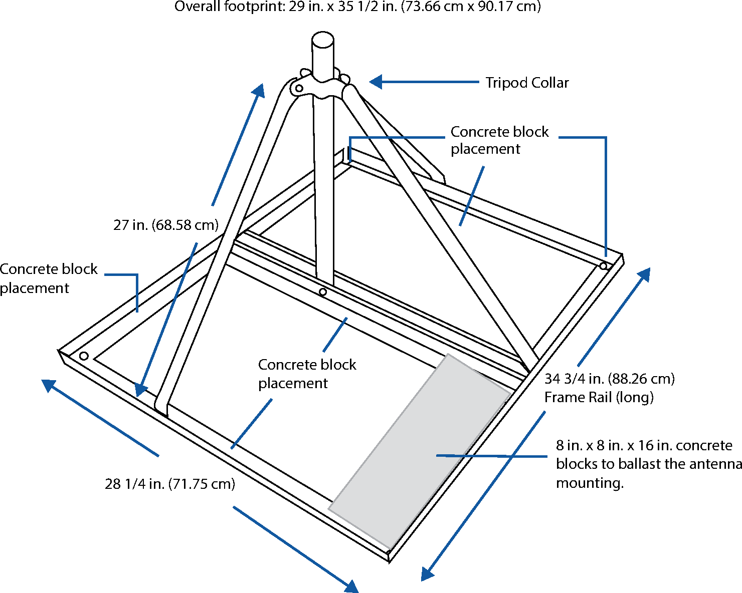
The Non-Penetrating Antenna Kit is designed for mounting a ground plane omnidirectional antenna when mounting to the side of a structure is not practical. The overall footprint of the frame is 29 inches x 35 ½ inches (73.66 cm x 88.9 cm).
Note
Installation requires six 8 in. x 8 in. x 16 in. concrete blocks (not supplied).
The kit is supplied with the following parts. If any of these items are missing, please contact Primex.
Description |
Qty |
|---|---|
Rigid galvanized conduit mast | 5 ft. x 1.25 inches (1.52 m x 3.17 cm) |
1 |
Tripod leg: 27 in. (2.54 cm) each in length |
3 |
Frame rail (long):34 ¾ in. (88.26 cm) |
2 |
Frame rail (short): 28 ¼ in. (71.75 cm) |
4 |
Grounding Clamp |
1 |
Long carriage bolt |
1 |
Short carriage bolt |
11 |
Flat washers |
12 |
Lock nuts |
12 |
Assemble non-penetrating antenna roof mount
Verify the kit contents.
Assemble the outer frame by laying the two long frame rails parallel to each - approximately 30 in. (76.2 cm) apart.
Insert a short carriage bolt from the bottom at each frame rail end, pointing skyward (4 total).
Connect the two long frames rails by placing the two short frame rails on top of the four protruding bolts to form a rectangle. Make sure the square holes in the short tail "sides" are directly opposite each other.
Place a washer and nut on each of the four bolts and finger tighten.
Position the tripod within the four-sided frame.
Secure the three tripod legs to the inside of the frame by inserting three short bolts, from the inside and placing the washer and nut on the outside of the frame.
Drop the bottom of the mast (end with hole) through the top of the tripod collar.
Place the remaining two short rails parallel to each other, separated by the bottom of the mast.
Align the hole at the bottom of the mast, with the two square holes in the short frame rail sides.
Insert the long bolt and connect the frame rails to the mast.
From the underside of the frame, insert the four remaining short bolts upward and connect the inner short tails to the frame.
Tighten all nuts to secure.
Use six 8 in. x 8 in. x 16 in. concrete blocks to ballast the antenna mounting. Blocks are to be placed from rail to rail on each side of the mast; three blocks per side with a single block placed on each end and one in the middle.
Penetrating antenna kit
The penetrating antenna kit contains the materials required to mount the antenna to a wooden pole or masonry wall. A 5/8 in. (1.58 cm) diameter mounting hole is required and the maximum diameter of the pole or wall thickness is 14 in. (35.56 cm).
The kit is supplied with the following parts. If any of these items are missing, please contact Primex.
Description |
Qty |
|---|---|
Rigid galvanized conduit section: 5 ft. x 1.25 in. |
1 |
Rigid galvanized conduit insert: 5 ft. x 1 in. |
1 |
Antenna mounting clamp |
2 |
Hex head bolt: 1/2 in. |
2 |
Bolt washer: 1/2 in. |
8 |
Lock washer: 1/2 in. |
8 |
Hex nut: 1/2 in. |
8 |
Mount antenna with penetrating antenna kit
Note
The recommended diameter of the pole or the wall thickness should not exceed 14 in. (35.56 cm).
Verify the kit contents.
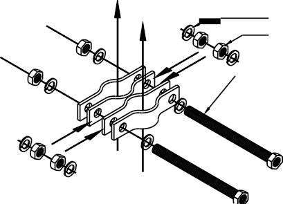
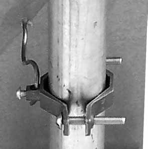
Assemble both clamps, as shown below, tightening the hex nuts to a torque of approximately 45 ft-lbs.
Remove the nut and washer from the 14 inch threaded rod.
Drill a 5/8 in. hole through the top of an exterior wall.
Insert the 14 in. threaded rod through the hole in the wall. If the thickness of the wall is greater than 10 in. a longer rod may be required. Different lengths of rod are available at hardware stores. If a longer threaded rod is needed, use a 5/8”-11 threads per inch rod.
Place the nut and metal plate over the rod.
Tighten the square nuts to an approximate torque of approximately 55 ft-lbs.
Drill a second 5/8 in. (1.59 cm) hole 2.5 ft. (0.76 m) directly below the first hole.
-
Ensure both clamps are vertically aligned, as shown below
Repeat Steps 4 through 6.
Connect the LMR 400 cable to the antenna. Be sure the connection is tight.
Insert the mast into the clamps.
Tighten both clamps evenly and securely.
Install a Gelwrap splice enclosure over the connection between the LMR400 cable and antenna. Secure Gelwrap to mast using common electrical tape or cable ties.
Next, route the antenna cable.
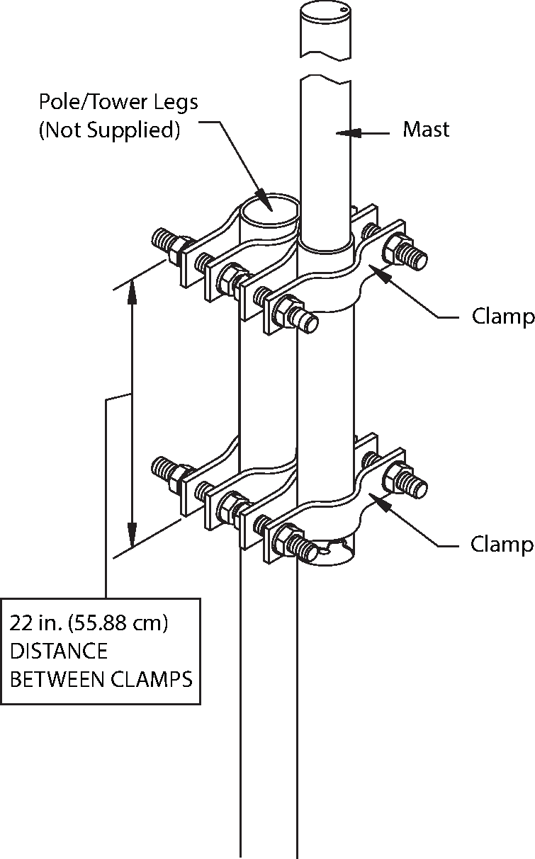
Pole mount kit
The antenna pole mount kit is designed for the purpose of mounting the antenna to round or angled tower legs.
The clamps can be used on round tower legs that measure from 1.25 in. to 3.25 in. (3.17 cm to 8.25 cm) OD or on angled tower legs that measure up to 3 in. (7.62 cm) on a side.
The center section of each clamp is welded to provide mechanical stability and all parts are hot-depped galvanized steel.
The kit is supplied with the following parts. If any of these items are missing, please contact Primex.
Description |
Qty |
|---|---|
Rigid galvanized conduit section: 5 ft. x 1.25 in. |
1 |
Rigid galvanized conduit section: 5 ft. x 1 in. |
1 |
X style clamp |
2 |
U-clamp |
4 |
1/2 inch all thread bolt |
4 |
1/2 inch lock washer |
16 |
1/2 inch hex nut |
16 |
Mount antenna using a pole mount antenna kit
Verify the kit contents.
Assemble both clamps, tightening the hex nuts to an approximate torque of approximately 45 ft-lbs.
Tighten half of one clamp two feet below the top of the pole. Use a 3/4 inch wrench to do this and be sure to tighten the clamps both evenly and securely.
Using a 3/4 inch wrench, tighten half of the other clamp a few in. below the top of the pole. Be sure to tighten the clamps both evenly and securely.
Connect the LMR 400 cable to the antenna. Be sure the connection is tight.
Insert the mast into the clamps. The bottom of the mast should be a minimum of 2 inches below the bottom clamp.
Using a 3/4 inch wrench, tighten all nuts on both clamps.
Next, route the antenna cable.
The National Electrical Code (NEC) requires that every antenna installation be grounded. Also many areas have local antenna grounding codes. Be sure that you are familiar with local grounding and other antenna regulations and codes.
Secure the ground clamp (supplied) around the antenna mast.
-
Insert and tighten the #6 gauge wire (supplied) in the ground clamp.
Note
Cut the wire off at the necessary length. The remainder of the wire will be used to ground the Transmitter.
Connect the other end of the #6 gauge wire to a verified building/earth ground.
A GPS Receiver is required when a Transmitter is set to use GPS as its time source.
Mount GPS Receiver
Verify the kit contents, and the install location meets the installation requirements.
From the outside of the building, route the GPS cable.
-
Assemble and mount the GPS Receiver unit to either the inside of a window (not Low-E glass) or to an outside pole or rooftop. The mounting location is required to have a clear view of the sky.
Note
Be sure to follow local building code requirements when attaching the GPS unit to the inside of a window. Clean the windowpane before using the suction cups for attachment.
Route GPS cable and connect to Transmitter GPS connection.
-
Mount Transmitter.
Verify all install requirements are met.
-
Attach External Antenna.
Connect the LMR 400 cable to the Transmitter "External Antenna" port, located on the backside of the Transmitter.
-
Establish an Ethernet connection (NETWORK LAN). Required for NTP time source and OneVue Monitor configuration.
Insert a network cable into the RJ-45 Ethernet port/Network LAN port. Plug the other end into a network Ethernet jack.
-
Connect GPS time source
Supplied Ferrite Bead is required to be attached to the GPS cable to prevent electromagnetic interference (EMI) between the Transmitter and GPS Receiver. Ferrite Bead should be located no greater than an inch from the end of the GPS cable – as near as possible to the Transmitter GPS IN input connection.
Attach the Ferrite Bead to the GPS cable within an inch from the end of the GPS cable.
Snap the ferrite choke closed. Be careful not to pinch the cable.
Using the supplied zip ties, secure a zip tie at each end of the ferrite choke to prevent it from slipping around the cable.
Plug GPS cable into the Transmitter "GPS IN" connection.
-
Connect AC power.
Connect the supplied AC power supply into the Transmitter AC power input. Plug the two-prong plug into a 120 VAC wall outlet.
During this step, wire the critical notification input source to the Transmitter contact closure terminal block. Additional details provided below.
Critical Notifications are triggered by an end user from the five-button Critical Notification Panel or by a third-party system hardwired to the main Transmitter's industry standard contact closure panel.
The critical notification events displayed on InfoBoards are commonly be defined by your facility's emergency response plan. By default these events are preset by Primex and can be customized with a OneVue Notify Monitor subscription. A customization is defined as a change made to the Primex preset characters displayed by InfoBoards during a critical notification event.
To customize the preset events displayed on InfoBoards, see topic Customize preset critical notification events. A customization requires validation of the hardwired interface and thorough testing must be performed.
The Critical Notification Panel requires a hardwired interface between its dry contact terminal block and the main Transmitter's dry contact closure terminal block. This interface provides the activation of critical notification events displayed on Notify InfoBoards.
A Critical Notification Panel has five individually controlled contact closure switches and one common ground. Each switch corresponds to the panel's five buttons that change the state of each switch. A switch state change is activated from a momentary button push, which triggers an input state change to the Transmitter dry contact closure terminal block over the hardwired interface. An input state change activates the corresponding event number that is immediately transmitted over the 72MHz wireless radio frequency. When an InfoBoard receives an event number, it displays the corresponding event number description stored locally on the InfoBoard.
The main Transmitter supports up to two parallel Critical Notification Panel interfaces. Each interface requires a single cable run between the Critical Notification Panel and the main Transmitter contact closure terminal block.
Wire Color* |
Panel Position (L to R) |
Transmitter Position (L to R) |
Activates Preset Event |
|---|---|---|---|
Green |
5 |
9 |
All Clear |
Gray |
4 |
7 |
Lockout |
Yellow |
3 |
5 |
Weather |
Blue |
2 |
3 |
Evacuate |
Red |
1 |
1 |
Lockdown |
Black |
SC |
10 |
n/a (common ground) |
* Per Primex supplied interface cable wiring color specifications. Isolate any non-used wires.
The last step is to configure the Transmitter with the OneVue Device Configurator (ODC) app. A Transmitter will not operate until it's configured.
OneVue Sync Transmitters can be configured for OneVue Monitor or for Standalone use. To receive remote support services from Primex, OneVue Monitor configuration is required. For Transmitters that are part of a OneVue Monitor subscription, they must be configured for OneVue Monitor use.