These instructions detail how to connect a Bell Controller's Relays to a public address (PA) or bell system, connect its dry contact closures to a standalone switch or button to activate an impromptu bell, and mount the device.
A bell controller has two independent relays that are connected to an existing PA or bell system. From OneVue, each relay is assigned to a bell schedule and the schedules are downloaded and stored in the bell controller device.
A bell controller's dry contact closure inputs can be connected to a standalone switch or button to activate a bell manually, commonly referred to as an impromptu bell. An impromptu bell is a bell event that is not scheduled in OneVue.
Download PDF Bell Controller Install Guide
Inspect the package contents to verify the supplied components are present and no damage has occurred during shipping.
Quantity |
Component |
|---|---|
1 |
Bell Controller Device |
1 |
AC power adapter. 5V DC USB Mini B (5 pin) connector interface, 5 ft (1.5 m) cable | Input: 100-240 VAC, 50/60 Hz, 0.4A | Output: 5V DC, 1.0A max. Optional power extension cable: USB power cable 6.5 feet (2 m), Mini B (5 pin) M and Mini B (5 pin) F connector. |
1 |
Primex 3.0v Lithium/Iron Disulfide Battery Pack (contains 2 AA 1.5V Energizer® Ultimate Lithium batteries). For backup power purposes only - device can operate on battery backup for up to a maximum of 24 hours. |
4 |
3M™ Dual Lock™ Tape, 2" x 1" strip |
1 |
USB configuration cable; supplied with each device order only. For use with the Primex Device Configuration software to manually configure a device or troubleshoot device network connectivity issues. It's recommended to save this cable for future use. |
Optional accessories: AC power extension cable
Before installing and connecting the device's terminal inputs to external equipment, be sure all requirements below are met.
-
For use with a public address (PA) and/or bell system equipment that supports a two-wire direct connection. Most systems provide for an auxiliary 2 wire connection to trigger pulse tones as an alternative to direct controls and audio options.
Consult with the PA or bell system manufacturer or integrator for more information or refer to the system equipment installation instructions for its input connection specifications.
Wiring of the bell controller terminal connections to a public address (PA) and/or bell system equipment must be performed by qualified personnel.
All wiring must comply with all local and national electrical codes, ordinances, and regulations. Failure to comply could cause serious electrical shock and damage to equipment that will void the warranty.
Relays are rated at a resistive load of 8A at 250VAC / 30 VDC and an inductive load of 3.5A at 250VAC / 30 VDC. Improper wiring can cause permanent damage to the Bell Controller device and/or the equipment to which it is connected. While these ratings provide a wide range of installation options, Primex recommends advance testing of any bell system prior to extensive product installation and conversion from any current solution.
When using multiple bell controllers to control different sets of bells within a facility, testing should be always be performed to confirm proper operation and to verify there is no bleed-over between multiple bell controllers. To prevent bleed over from occurring, the best practice is to have a single bell controller per branch circuit.
Bell controller terminals accept wire gauge from 16-26 AWG.
When wiring the bell controller to a public address (PA) and/or bell system equipment, all power to the device and equipment must be turned off.
Bell controller must be installed indoors.
Bell controller must not be used for medical, life-saving purposes, or for any purpose where its failure could cause serious injury or the loss of life.
Bell controller must not be used in any way where its function or failure could cause significant loss or property damage.
Bell controller must be configured with your OneVue account ID and network settings. Verify the device can successfully connect to the network and check-in to OneVue at its install location.
When identifying the mounting location of a bell controller, consider the following guidelines.
Requires a hardwired connection from the bell controller's terminal block to an existing PA or bell system, the two must be in close proximity to each other.
Wired Ethernet use: network port jack is located in close proximity to the install location.
Power over Ethernet (PoE) use: PoE compliant network port jack is located in close proximity to the install location.
AC power: an outlet is within 5 feet (1.52 m) from the install location.
Install location is easily accessible for maintenance and clear from obstructions.
Bell controller is shock and vibration resistant; however, be careful not to drop or install the device in a location where it could be exposed to excessive vibration.
A Bell Controller has two independent relays that can be connected to your existing PA or school bell system. Each of the relays has a separate Normally Open (NO) and Normally Closed (NC) input.
The removable terminal connector is provided for simple wiring. The wiring procedure is as follows:
Be sure to follow the installation requirements and installation location guidelines.
All power to the device and PA or bell system equipment must be turned off.
-
Remove the terminal connector from the device and make the wiring connections to the terminals.
Make sure the wires are properly attached to the terminals and the terminal connections are tight. Wires are to be stripped and there are no loose strands that can cause a short.

P3: Relay 1 Normally Closed Contact Input
P4: Relay 1 Common Contact Input
P5: Relay 1 Normally Open Contact Input
P6: Relay 2 Normally Closed Contact Input
P7: Relay 2 Common Contact Input
P8: Relay 2 Normally Open Contact Input
Terminals accept wire gauge from 16-26 AWG.
Reconnect terminal connector to the bell controller.
Apply power to the bell controller; AC or PoE.
The Bell Controller dry contact closure inputs can be connected to a standalone switch or button to activate a bell manually, commonly referred to as an impromptu bell. An impromptu bell is a bell ring event that is not scheduled in OneVue.
The removable terminal connector is provided for simple wiring. The wiring procedure is as follows:
Be sure to follow the installation requirements and installation location guidelines.
All power to the device and equipment wiring the device to must be turned off.
-
Remove the terminal connector from the device and make the wiring connections to the terminals.
Make sure the wires are properly attached to the terminals and the terminal connections are tight. Wires are to be stripped and there are no loose strands that can cause a short.
P1: Input 1 for the impromptu bell (switch or button input) – dry contact closure input pair sounds bell(s) on both relays immediately when activated
P2: Input 2 for the impromptu bell (switch or button input)
Terminals accept wire gauge from 16-26 AWG.
Reconnect terminal connector to Bell Controller.
Apply power (AC or PoE) to Bell Controller.
A Bell Controller can be mounted to the outside surface of a fixture, wall, or another type of unit using the supplied 3M™ Dual Lock™ Tape strips.
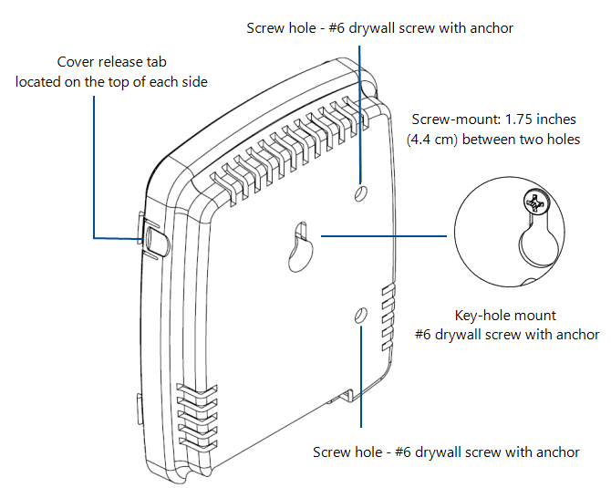
Remove the device cover; simultaneously press the two tabs located on the top side of the device.
Insert the 3.0v Primex Lithium/Iron Disulfide Battery Pack or two 1.5v Lithium AA batteries. Follow the symbols showing the correct way to position the positive (+) and negative (-) ends of the battery pack.
Located to the lower-right of the battery compartment, set the battery on/off switch to the Up (On) position.
Replace the device cover.
Prepare the mounting area to ensure maximum adhesion. If there is moisture, dry the area first.
Apply two pieces of the supplied 3M™ Dual Lock™ Tape to the back of the device; top and bottom, horizontally centered.
Apply two pieces of the supplied 3M™ Dual Lock™ Tape to the mounting surface; align with the device tape position.
-
Affix the device to the mounting surface.
It's recommended to dress the cables with self-adhesive hook-and-loop mounting tape.
Apply power to the bell controller; AC or PoE.
-
When power was applied, the device automatically initiated a check-in to OneVue. Verify its LCD displays Signal OK, which indicates it successfully checked-in to OneVue.
If the LCD screen does not display Signal OK, it's recommended to initiate a manual check-in to validate the device can connect to the facility network and OneVue at its install location. Press and release its check-in button
 . The device emits a series of audio beeps indicating its connection sequence.
During an active check-in connection, additional pressing of the check-in button is ignored.
A Bell Controller can be mounted directly to a wall surface by way of a key-hole mount or screw mount that n be applied with the use of two #6" drywall screws and anchors.
Remove the device cover; simultaneously press the two tabs located on the top side of the device.
Insert the 3.0v Primex Lithium/Iron Disulfide Battery Pack or two 1.5v Lithium AA batteries. Follow the symbols showing the correct way to position the positive (+) and negative (-) ends of the battery pack.
Located to the lower-right of the battery compartment, set the battery on/off switch to the Up (On) position.
Replace the device cover.
-
Determine the mounting location by referencing the key-hole slot located on the back of the device.
Mark and pre-drill a mounting hole into the solid and level wall surface.
Insert wall anchor into the mounting hole.
Insert a screw into the wall anchor, leaving approximately 3/8” of the screw head exposed for hanging.
Attach the device to the wall surface by sliding the key-hole slot onto the mounting screw. Ensure the device is properly secured and level.
Apply power to the bell controller; AC or PoE.
-
When power was applied, the device automatically initiated a check-in to OneVue. Verify its LCD displays Signal OK, which indicates it successfully checked-in to OneVue.
If the LCD screen does not display Signal OK, it's recommended to initiate a manual check-in to validate the device can connect to the facility network and OneVue at its install location. Press and release its check-in button
. The device emits a series of audio beeps indicating its connection sequence.During an active check-in connection, additional pressing of the check-in button is ignored.