This topic provides the requirements and procedures to install a 1 Watt XR Transmitter with an internal antenna.
For a system with more than one Transmitter, first configure and install the main Transmitter and verify it received a valid time signal and then configure Repeater Transmitters. When all Transmitters are configured and installed, you can then configure and install the system clocks or InfoBoards.
Do not install system clocks and other devices until Transmitter and its components are installed and configured; powered on, time source configured and valid time signal received, and fully operational.
Review all installation requirements and identify the installation location of the Transmitter and system components.
Review all Safety Instructions and Warnings.
Inspect system components to verify packaging includes all supplied parts for each system component and verify no damage has occurred during shipping.
The following tools and equipment are recommended and can be purchased from Primex.
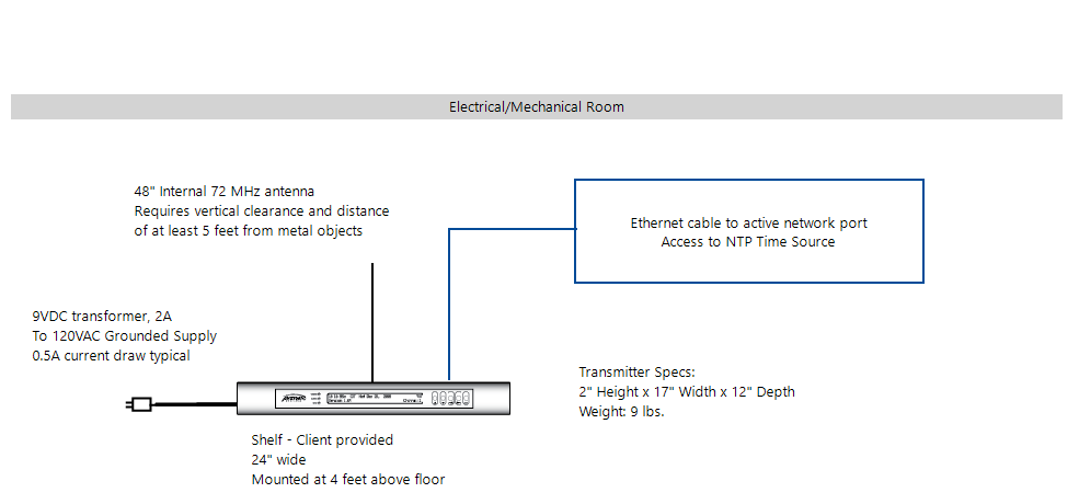
1 Watt Transmitter Shelf. 18 GA metal, epoxy coated, 18 in. L x 3 in. H x 16.5 in. D
Uninterrupted Power Supply (UPS)
Location and mounting must meet all of the following requirements.
Multi-story building: locate main Transmitter on the top floor; significantly improves coverage to the lower floors due to the “umbrella” pattern of transmission
Transmitter mounting location: a minimum of 4 ft. (1.2 m) above the floor.
Transmitter shelf mounting: 18 in.L x 3 in. W x 16.5 in. mounting shelf available from Primex.
-
Transmitter enclosure clearance: located in an area that allows for required clearance.
Enclosure dimension: 2 in. H x 17 in. W x 12 in. D (5.08 cm x 43.18 cm x 30.48 cm). Required wall area is 24 in. W x 18 in D.
Allow a minimum of 43 in. (1.09 m) vertical clearance; includes internal antenna 40.8 in. H (1.03 m) and Transmitter enclosure height of 2 in. (5.08 cm)
Internal antenna clearance: requires vertical clearance and distance of a minimum 5 ft. (1.5 m) from large, solid objects, such as lockers or filing cabinets. Antenna should never make contact with metal objects, especially electrical conduit or wiring of any kind, and proximity to these should be avoided. Internal Antenna height: 40.8 in. (1.03 m).
-
AC power: located within 5 ft. (1.5 m) from a 120 VAC electrical outlet. 10 AMP dedicated service recommended.
AC power supply (supplied): Input: 120 VAC, 50/60 Hz, 0.6 Amp. Output: 9 VDC, 1.78 Amp. 6 ft. (1.83 m) cord
Environment: located in an indoor controlled environment that is 32° to 122° F (0° to 50° C) and a non-condensing humidity environment.
GPS Receiver location
Must be mounted where it has a "clear view of the sky" to receive a GPS signal 24 hours a day.
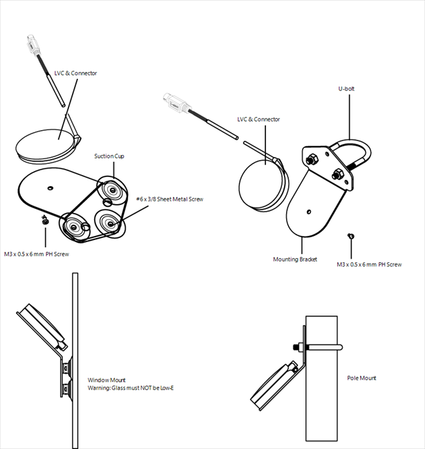
Typical mounting locations include the inside of a window (not a Low-E glass window), to an exterior pole, or on a rooftop.
Must be kept away from large metal objects.
GPS Receiver and cable must be mounted above any potential standing water, snow depth, leaves or other obstructions and is protected from the weather.
GPS cable
10 ft. (3 m) GPS cable supplied. Extension cables available from Primex.
Maximum total distance of the GPS cable to the Transmitter cannot exceed 200 ft. (60.96 m).
GPS cable located outdoors: cable routing to the inside of the building requires 2 in. (5 cm) minimum conduit and weatherhead. The use of a GelWrap splice enclosure is strongly recommended.
GPS and extension cables connections must be weatherproofed.
The following tools and equipment are required to complete installation.
Standard or hammer drill
5/8 inch concrete drill bit, 18 in. (45.7 cm) long
Silicone caulk for GPS cable penetration
Phillips screwdriver
Slotted/Flat Head screwdriver
A GPS Receiver is required when a Transmitter is set to use GPS as its time source.
Mount GPS Receiver
Verify the kit contents and the installation location meets the installation guidelines.
-
From the outside of the building, route the GPS cable.
Transmitter with Internal Antenna: route through a 5/8 inch drilled hole into the building.
Transmitter with External Antenna: route through a 3/4 inch drilled hole into the building.
-
Assemble and mount the GPS Receiver unit to either the inside of a window (not Low-E glass) or to an outside pole or rooftop. The mounting location is required to have a clear view of the sky.
Note
Be sure to follow local building code requirements when attaching the GPS unit to the inside of a window. Clean the windowpane before using the suction cups for attachment.
Route GPS cable and connect to Transmitter GPS connection.
Configure a Transmitter to use a NTP time source
Located on the back of the Transmitter, set the dip switch settings to the firmware version.
Insert one end of an Ethernet cable into the Ethernet port located on the back of the Transmitter and the other end into a port on the facility's Ethernet network.
Apply power to the Transmitter.
-
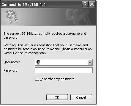
From your computer open a web browser, recommend use of Firefox is strongly recommended, and from the address bar enter the Transmitter factory default IP address: http://192.168.1.1
If the Transmitter IP address has been changed from the factory default address, complete steps in section below Set Transmitter temporary IP address during NTP configuration. Once complete, proceed with following step.
Note
Your computer is required to be on the same subnet as the Transmitter (for example: 192.168.1.10).
-
The Connect To dialog window is displayed. Leave both user name and password blank, click OK to log into the Transmitter.
-
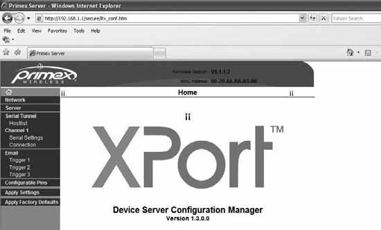
The XPort Device Configuration Manager screen is displayed.
-
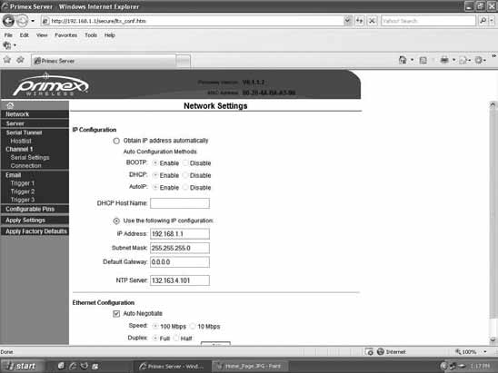
Click Network. The Network Settings screen is displayed.
-
To change the factory default static IP address, set the options in the Network Settings screen.
To use DHCP, select “Obtain IP address automatically”. You must also enter the DHCP Host Name.
To use a static IP address, select “Use the following IP configuration” and enter the IP Address, Subnet Mask and Default Gateway.
Be sure to write down and file the changes you make to the network configuration settings. Once the default static IP address is changed, the factory-default IP address will no longer work and you must use the new settings to access the Transmitter configuration.
(Optional) Enter the IP address of the NTP server to set the Transmitter's time source.
Click OK.
-
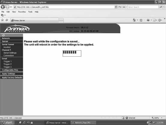
Click Apply Settings on the configuration frame.
The Transmitter automatically reboots (restarts). The window below is displayed.
The setting panel is located on the back of an XR Series Transmitter. The setting panel consists of dial and dip switch settings that set its channel number, time zone, and time source.
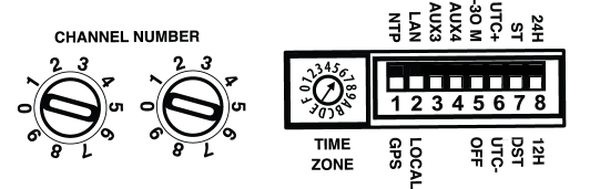
Channel Number
Preset by factory. The Channel Number is set according to the FCC license; do not attempt to change without contacting Primex.
Time Zone
-
Transmitter with Internal Antenna: Set the Time Zone dial to your system Time Zone using the dial Time Zone switch.
Time Zone dial switch specifications
Time source and time settings
Set the Transmitter dip switch settings below to meet the system requirements.