Inspect the package contents to verify the supplied components are present and no damage has occurred during shipping.
Quantity |
Component |
|---|---|
1 |
Water Leak Sensor |
1 |
Water Detector |
1 |
AC power adapter: 5V DC USB Mini B (5 pin) connector interface, 5 ft (1.5 m) cable, Input: 100-240 VAC, 50/60 Hz, 0.4A, Output: 5V DC, 1.0A max |
1 |
Primex 3.0v Lithium/Iron Disulfide Battery Pack (contains 2 AA 1.5V Energizer® Ultimate Lithium batteries) |
2 |
3M™ Dual Lock Fastener & Tape, 2" x 1" strips |
1 |
USB configuration cable; supplied with a device order only. For use with the Primex Device Configuration software to manually configure a device or troubleshoot device network connectivity issues. It's recommended to save this cable for future use. |
The location of the sensor and detector impacts its use and operation. Be sure to identify a location that meets the following guidelines. For mounting illustrations, see topic Water Leak Sensor application uses.
Water Leak Sensor location
Sensor is not water-resistant or waterproof. Mount at a minimum of 3 ft. (0.91 m) above floor level; avoid exposing device to water.
Water Detector placement
A Water Detector can be placed directly on a floor surface for low-water level detection or above the floor for higher water-level detection.
-
Ensure placement surface is smooth and clean.
If the unit’s metal contacts come into contact with a foreign material (oil, detergent, etc.), then contacts may repel water and therefore will not be able to properly detect water.
-
Locate in an area that does not allow the cable to be excessively pulled, bent, or placed under heavy objects.
To secure cable, standard plastic U-clip or half U-clip with an adhesive base can be used.
-
Low-level water detection
Water Detector must be placed on the floor with the logo facing the ceiling and the bottom side two metal contacts facing down on the surface.
-
High-level water detection
Water Detector must be placed vertically with the logo facing you and the bottom two metal contacts facing down towards the area being monitored.
Connecting multiple Water Detectors
For larger areas, it’s recommended to daisy chain up to four Water Detectors along the entire perimeter of the floor or in the area where the assets being monitored are located. Each Water Detector has an input that allows for connecting multiple water detectors in a series to monitor larger areas.
A single Water Leak Sensor allows up to four connected Water Detectors.
To prevent damage to the Water Detector components the input plug should remain in place while not in use.
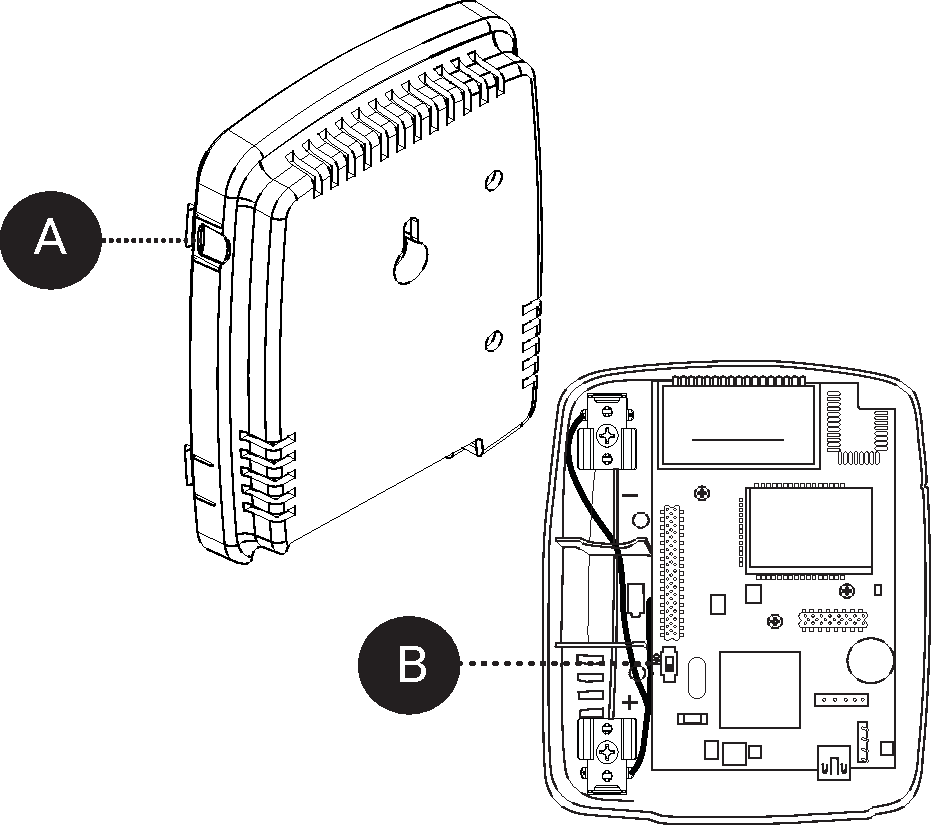
Remove the device cover; simultaneously press the two tabs located on the top side of the device (A).
Insert the 3.0v Primex Lithium/Iron Disulfide Battery Pack or two 1.5v Lithium AA batteries. Follow the symbols showing the correct way to position the positive (+) and negative (-) ends of the battery pack.
Located to the lower-right of the battery compartment, set the battery on/off switch to the Up (On) position (B).
-
Replace the device cover.
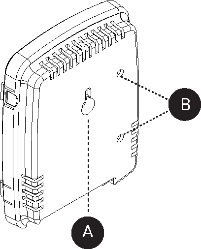
Mount sensor using either of the methods below.
Method |
Steps |
|
|---|---|---|
Wall mount |
Key-hole mount (A)
Two-screw mount (B)
|
|
|
Surface mount 3M™ Dual Lock Fastener & Tape, 2" x 1" strips |
|
Place it where you expect there could be a water leak or unwanted water using either of the below methods. When water reaches both metal contacts, activates a change to the voltage reading measurement (Wet) that is then received by Water Leak Sensor.
Detection |
Mounting method |
Low-water level detection |
|
Higher water-level detection |
|
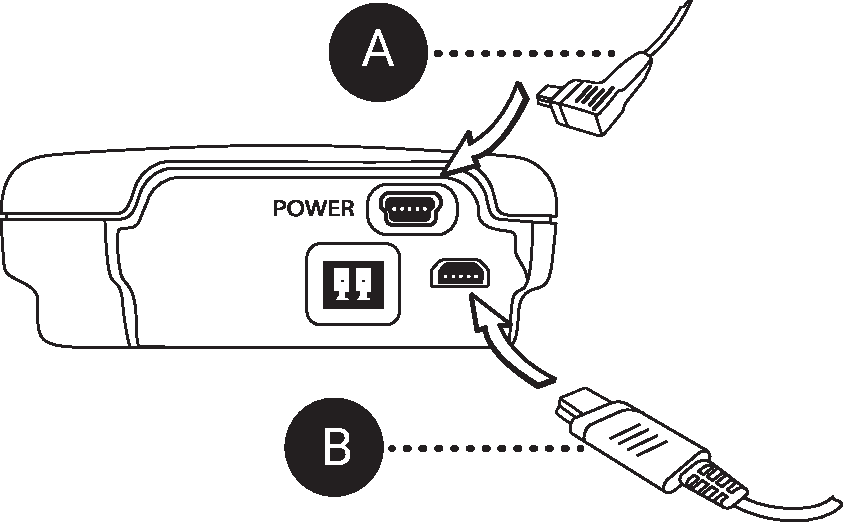
Connect AC power (A). For PoE model, connect Ethernet cable to sensor Ethernet port.
-
Connect Water Detector to sensor device (B).
A Water Leak Sensor does not monitor for water until it has connected to OneVue.
Verify Signal OK is displayed on the LCD screen, which indicates it successfully checked-in. When power was applied, the sensor initiated a check-in to OneVue.
-
If Signal OK is not displayed, initiate a manual check-in. From the front of the sensor, press and quickly release the check-in button
 (up arrow). The sensor emits a series of audio beeps indicating its connection sequence. During an active check-in connection, additional pressing of the check-in button is ignored.
Verify the following settings are configured to meet the requirements of the condition being monitored.
-
Monitored Asset settings. Go to Monitoring > Monitored Assets.
Each Primex sensor is assigned to a Monitored Asset and its readings or monitored conditions generate the current and historical readings for the asset. In addition, sensor operating condition data is linked to its assigned Monitored Asset. When a sensor enters a Warning or Alarm state, its assigned Monitored Asset is also set to an Alarm or Warning state.
Sensor assigned to a Monitored Asset. Go to Devices > Sensors > select sensor > verify assigned Monitored Asset.
Monitored Asset assigned to sensor is added to an Alert Rule.
Monitored Asset assigned to sensor is added to a Report Profile.
Users responsible for the monitored condition are assigned to Monitored Asset's Business Unit.
-
Sensor settings (Go to Monitoring > Monitored Assets > select Monitored Asset > select sensor.
-
Alarm Delay
By default, set to 0 (zero). A Wet reading automatically results in an Alarm state.
The Alarm Delay is the amount of time OneVue delays setting the sensor and Monitored Asset to an Alarm state when in an Out of Range status. When it remains in an Out of Range for the time period set in its Alarm Delay setting, the sensor and its Monitored Asset are set to an Alarm state with a status of Out of Range, Past Alarm Delay.
-
Audio Alert (sensor gateway setting)
Primex sensors are equipped with a reading alarm audio alert. The audio alert is activated when a reading is out of range and the time period it has been out of range has exceeded the time period set in its Alarm Delay. Be default, the audio alert is disabled.
By default audio alert is disabled.
-
Logging Interval (sensor gateway setting)
The Logging Interval is how frequent a sensor logs a reading and stores it into its internal memory. All logged readings are then sent to OneVue at the frequency set the sensor's Check-in Interval frequency.
By default set to 1 hour.
-
Check-in Interval (sensor gateway setting)
The Check-in Interval is the frequency a sensor connects to the facility's network to send its logged readings to OneVue. Also during each check-in, pending setting updates are downloaded to the sensor.
By default set to 8 hours.
-
Unresponsive Timeout (sensor gateway setting)
The Unresponsive Timeout is the maximum amount of time a Primex device can go without a check-in to OneVue. When this time limit is exceeded, the device is set to an Alarm state with an Unresponsive status.
By default set to 16 hours.
-
Test triggering a Wet reading at the time of installation; H2O displayed on LCD screen and Wet reading is transmitted to OneVue.
Detects water bridge across the two metal contacts located on the bottom side of the Water Detector. A change to the voltage reading measurement detects a dry or wet condition. When water reaches both metal contacts, activates a change to the voltage reading measurement that is then received by Water Leak Sensor.